KiCad plugin
This page is under construction
The kicad-kbplacer is KiCad plugin for placing and routing keyboard matrix switches and diodes. It is meant to accelerate design process by removing repetitive tasks. It is not the only tool of this kind1 but it is currently amongst the most popular choices.
This page is not the guide on mechanical keyboard PCB design. Prior knowledge about using KiCad is expected. The purpose of this document is to demonstrate kicad-kbplacer capabilities, show how it can be used for some common keyboard related tasks and how to solve possible problems.
Installation
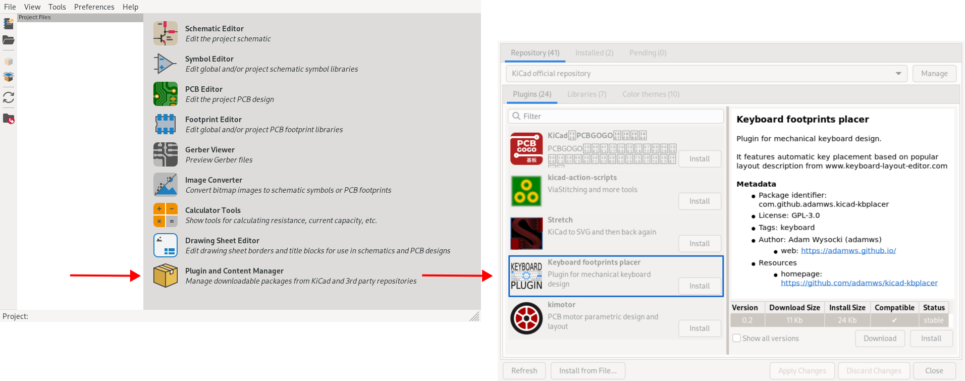
Use KiCad's Plugin and Content Manager and search for Keyboard footprints placer. Select latest version and click install.
After installation, plugin can be started by clicking plugin icon on the toolbar of KiCad's PCB editor:
If it does not appear on the toolbar (which may happen when application window is to small), go to Tools -> External Plugins menu.
KiCad plugins are accessible only from PCB editor (pcbnew) and not from schematic editor (eeschema).
Usage
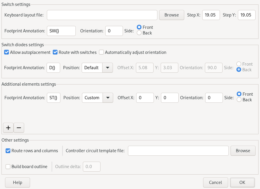
When started, plugin will greet you with following settings window:
Following chapters will explain most of these settings in detail. For complete description refer to plugin's README.
All of the following sections assume that you have imported footprints to PCB editor. In most workflows it means that schematic is ready and fully annotated. There are some important considerations regarding matrix annotation but this will be explained later.
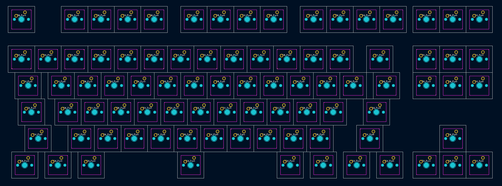
How to arrange elements according to layout from keyboard-layout-editor
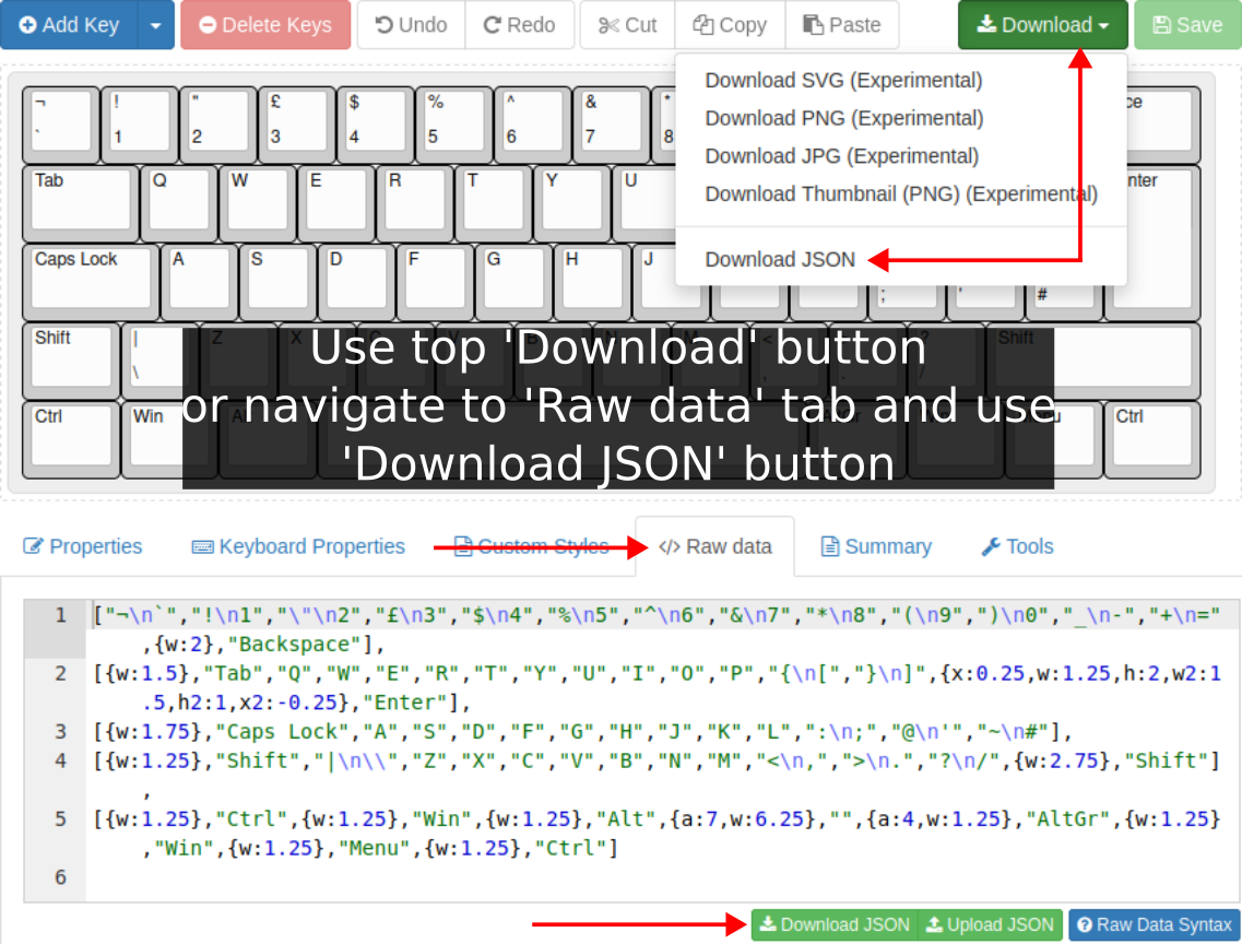
The keyboard-layout-editor is de-factor community standard for designing layouts. The kicad-kbplacer can use it to arrange footprints. First you must download json layout file:
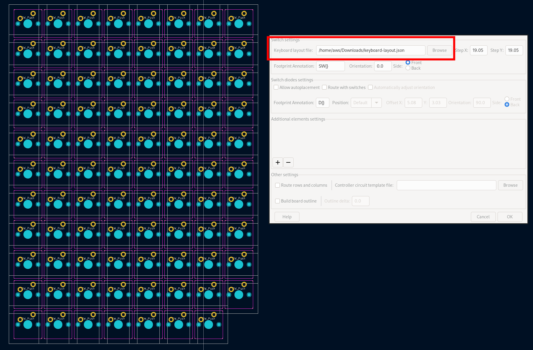
Then run kicad-kbplacer and choose downloaded file in Switch settings -> Keyboard layout file option. Make sure that Switch settings -> Footprint Annotation value matches your annotations. Otherwise plugin won't be able to locate switch footprints. Other options settings might be ticked off/left default.
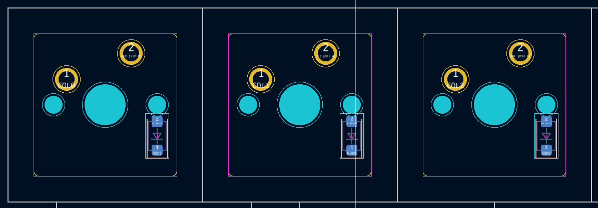
How to change the position of all switch diodes
Use Switch diodes settings -> Allow autoplacement checkbox. Layout file field might be empty.
All diodes will be moved to switch-relative position defined by Position dropdown and position fields. When Default selected then position fields are inactive.
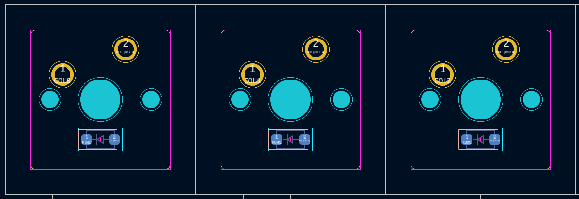
Note that default position might not be suitable for used diode footprint. This is the case in the above example. The diodes pads are too close to drill holes. This can be fixes by running plugin again but this time with different position. For example:
This step can be combined with switch placement action
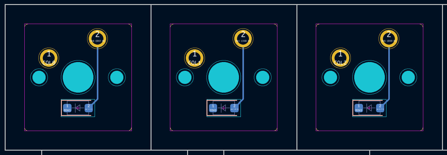
How to use routing
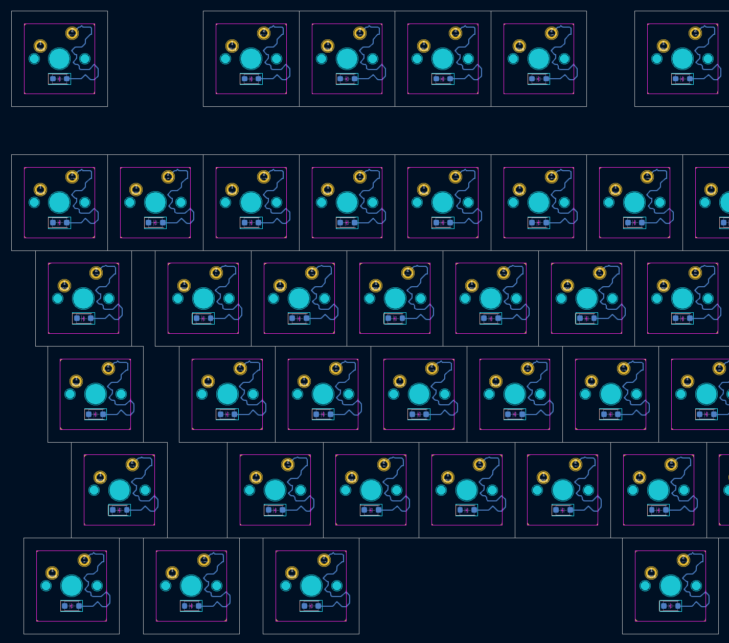
Run with Switch diodes settings -> Route with switches option enabled.
If you are not happy with routing result just press Edit -> Undo. Plugin should not break KiCad's undo/redo capability.
The kicad-kbplacer does not implement proper auto-router. Not all switch footprint and diodes position combinations will work. For more control use track templates described in next chapter.
This step can be combined with switch and diodes placement actions
How to define and use track routing template
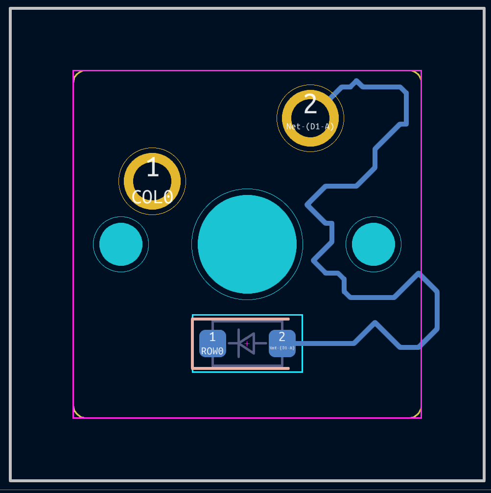
You can teach the plugin how to route. Just route first switch - diode pair by hand:
and run same as in previous section.
This is just an example to show that template can be anything you want. Plugin may struggle when using template with so many segments and it might take a long time.
How to place LEDs
[todo]
